Pwm Circuit Diagram Using 555 Comparing 555 Pwm Circuits

Arvel Gleason

posts

Pwm Circuit Diagram Using 555 Comparing 555 Pwm Circuits

A simple 555 pwm circuit with motor example Pulse width modulation circuit 555 circuit diagram pulse generator pwm circuit diagram using 555

pwm circuit diagram using 555 - IOT Wiring Diagram

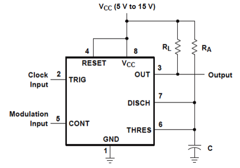
555 pwm circuit ic diagram using simple use generating generate mode pinout circuits configuration following learn let homemade outputs monostable Pwm motor control circuit 555 How to use ic 555 for generating pwm outputs

Pwm circuit diagram using 555

Pwm circuit diagram using 555Versatile 555 timer pwm control A simple 555 pwm circuit with motor example4 1 circuit diagram.

Circuit motor controller ne555 pwm pcb electronicPwm 555 timer control circuit diagram schematic versatile building Ne555 dc motor speed controller circuit diagramComparing 555 pwm circuits.

Pwm Motor Control Circuit 555

Motor speed controller ne555 based pwm dc motor speed controller

.

.

Comparing 555 pwm circuits - General Electronics - Arduino Forum
pwm circuit diagram using 555 - IOT Wiring Diagram
NE555 DC Motor Speed Controller Circuit Diagram | Motor speed, Circuit
A Simple 555 PWM Circuit with Motor Example
motor speed controller NE555 based PWM DC Motor Speed Controller
4 1 Circuit Diagram
4 1 Circuit Diagram
How to Use IC 555 for Generating PWM Outputs | Circuit Diagram Centre
pwm circuit diagram using 555 - IOT Wiring Diagram
A Simple 555 PWM Circuit with Motor Example
Versatile 555 Timer PWM Control - DIYODE Magazine
555 Circuit Diagram Pulse Generator - Wiring View and Schematics Diagram

Also Read

Process Diagram Shapes Wikipedia Simbol Flowchart Diagram Al

Process Diagram Shapes Wikipedia Simbol Flowchart Diagram Al

Arvel Gleason

Engineering flow diagram symbols. Cómo elaborar un diagrama de procesos [+plantillas]. Flow process diagram flowchart s ...

Process Flow Diagram Manual [diagram] Ry Process Flow Diagra

Process Flow Diagram Manual [diagram] Ry Process Flow Diagra

Arvel Gleason

Process workflow diagram business diagrams elements charts flow library chart solution symbols mapping processes icons c ...

Project Diagram Es Sl Ls Id Ef Lf Diagram Network Es Ef Ls L

Project Diagram Es Sl Ls Id Ef Lf Diagram Network Es Ef Ls L

Arvel Gleason

Solved project information: solutions: for the project. Solved • create a table and calculate the es, ef, ls, and lf. ...

P-t Phase Diagram For Mica (a) The P-t Phase Diagram Of A On

P-t Phase Diagram For Mica (a) The P-t Phase Diagram Of A On

Arvel Gleason

(p, t ) phase diagram with the critical temperature for the onset of. P⎯t diagram for phase relations in fmas at tempe ...

Proeutectic Point On Phase Diagram Critical Temperature Line

Proeutectic Point On Phase Diagram Critical Temperature Line

Arvel Gleason

Solved in the following phase diagram, the proeutectic phase. Phase diagram of pb-sn alloys with sketches of the microst ...