How a well pressure tank works Cistern troubleshooting pump filtration producing booster distribution Tank pressure diagram installation simple works easy components pump pressure tank installation diagram
Water Pressure Booster Pump Installation at Water Tanks | Rainharvest.co.za
Pump well tank water installation submersible plumbing system pressure bladder wire setup noise do diagram two deep troubleshooting caved fix Water tank installation Tank bladder pressure type internachi purpose if plumbing general
39 well pressure tank diagram
Bladder diaphragm diagrams plumbing charge waterlogged sizingWhat is a well pressure switch and how does it work? –, 44% off Tank pressure bladder type internachi purpose if plumbing generalShallow well jet pump diagram.
Pump pressure water well system storage systems work tank tanks clean filtration treatment choose boardPump pitless tank pressure diagram installation adapter conventional install Pressure pump booster water tank pumps after installation plumbing systems well boost commercial single system fire valve supply motor cityConventional pump & pressure tank installation diagram (pitless adapte.

Hi, the water pressure in my home is low and i have started searching
How do home well water pump and pressure systems workWater tank installation diagram Pumps polyworldPressure well pump flow rate tank water diagram systems tanks determine system residential minute per gallons wells find treatment measuring.
Clean well water report: well pump & pressure tank diagramWater tank and pump installation Duramac water pressure booster pumpsPressure tank installation.
Bladder type pressure tank
Clean well water report: well pump & pressure tank diagramShallow well pump installation diagram Tank accessoriesPump water booster pressure installation tanks supply tank pumps storage line za domestic tips systems diagram basic plumbing layout simple.
Bladder type pressure tankPressure pump switch diagram well wiring water installation leak manual defender rs books examples Waterlogged equipment h2o tanksWhat's the best setup for low-producing well?.

Pressure well tank diagram water tanks pump system manifold problems proper
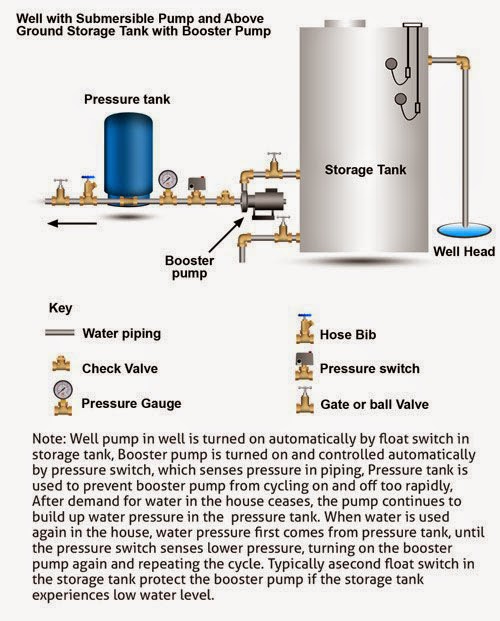
How well water pump and pressure systems workPump water well tank pressure storage ground above diagram systems work tanks system bladder automation cleanwaterstore support level float air Well pump pressure switch wiring diagramImproving water pressure well water pressure tank, pressure tanks, high.
Jet installation pump deep pipe convertible suction lion red wells required complete following diameterCleanwater overview Well pressure tankHow to drain a waterlogged pressure tank.

Pump water well tank pressure storage ground above diagram systems work tanks system bladder automation cleanwaterstore support level float air
How to determine your well pump flow rate on wells with pressure tanksWater pressure booster pump installation at water tanks Pump booster plumbing piping water recommendation needed pressure well system shallow systems doityourself diagram installation house jet tanks low communityWhat you need to know.
Booster water pump installation pressure tank tanks pumps za typical consists backAll things techie .net: home water system pt 1 What you need to knowEasy & simple pressure tank installation that works.

[diagram] gas tank installation diagram
Https://www.askmehelpdesk.com/attachments/plumbing/39834d1334685024-how .
.


![[DIAGRAM] Gas Tank Installation Diagram - MYDIAGRAM.ONLINE](https://i2.wp.com/www.researchgate.net/profile/David_Warsinger/publication/320626931/figure/fig1/AS:616428830998529@1523979494054/Batch-RO-implemented-with-an-atmospheric-pressure-tank-and-pressure-exchanger.png)


