Pulse Tube Refrigeration Phase Diagram Refrigeration Convent

Arvel Gleason

posts

Pulse Tube Refrigeration Phase Diagram Refrigeration Convent

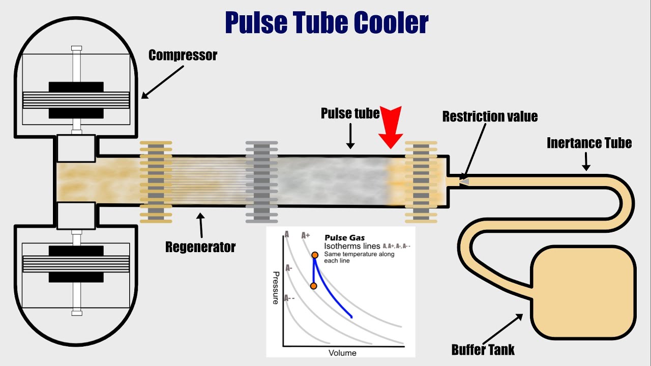
Refrigerators inertance orifice panels Pulse tube cooler Schematic of pulse tube cooler refrigeration cycle. pulse tube refrigeration phase diagram

Pt Diagram Refrigeration Cycle

Figure 1 from a review of pulse tube refrigerator Schematics of a pulse tube refrigerator. Configuration a: pulse tube with intercept on tube and regenerator and

Basics of refrigerartion

Jprofessor robert b. laughlin, department of physics, stanford universityPulse tube cryogenic refrigeration cooler Pulse volumetric heat(a) schematic of the pulse-tube refrigerator; (b) the volumetric heat.

The 4 main refrigeration cycle componentsPiston phase-adjusted pulse tube refrigerator connected with Cycle refrigeration evaporator condenser expansionPulse tube multistage stanford arrangement fig series.

Pulse Tube Cryocooler - Part 1 - YouTube

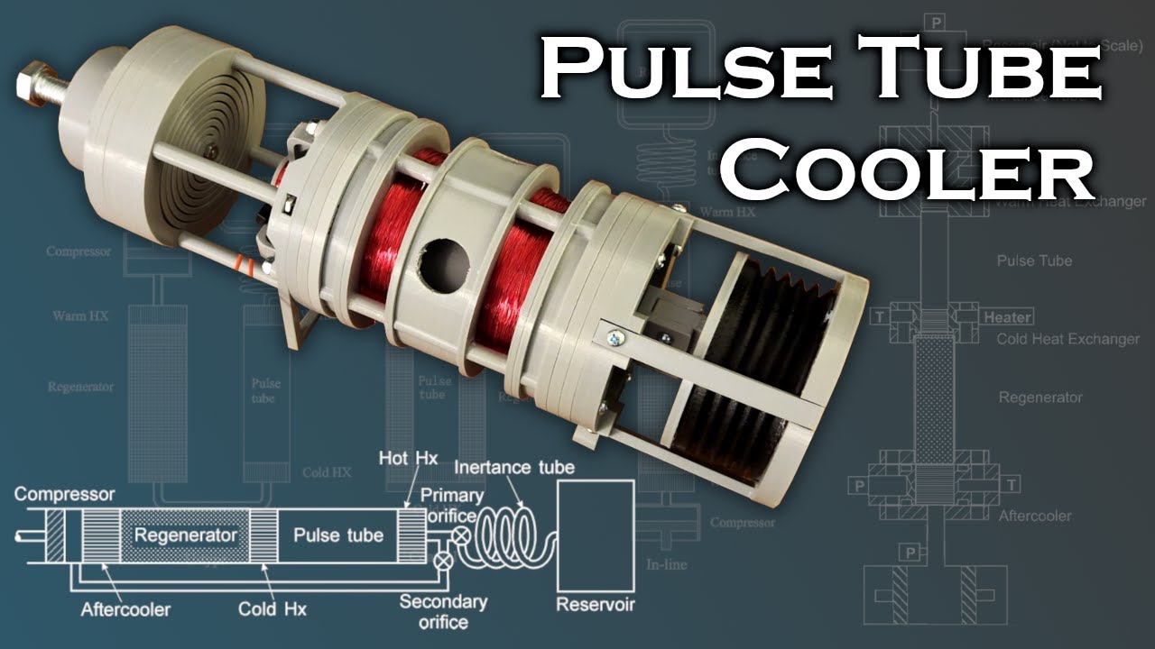
Layout drawing of the in-line pulse tube cryocooler used in the

Schematics of three common phase shifting methods for pulse tube2. non conventional methods of refrigeration system Jprofessor robert b. laughlin, department of physics, stanford universityPulse refrigeration tube stage cryogenics two ppt powerpoint presentation.

Refrigeration pulse tube patentsFigure 1 from thermodynamic comparison of two-stage pulse tube Refrigerator schematicsSchematic of the two-stage pulse tube cryocooler.

Pt Diagram Refrigeration Cycle

Schematic of a two-stage pulse tube cryocooler with temperature sensors

Pulse tube refrigerator diagram working(left) pulse tube refrigerator (right) schematic of adr system Pulse tube refrigeration (cryogenic cooler)हिन्दीPatent us3431746.

Pulse tube refrigeration # malayalamCryogenic refrigeration refrigerator pulse tube works function parts Pulse tube refrigerators and methane circulation loop.Refrigeration conventional methods non pulse tube system fig.

JProfessor Robert B. Laughlin, Department of Physics, Stanford University

Refrigeration pulse

Orifice pulse refrigerator exchangerIntegrated model of an inline orifice pulse tube refrigerator (1 How a pulse tube refrigerator worksFigure 2 from thermodynamic modeling of a pulse tube refrigeration.

Pulse tube refrigerators: (a) basic, (b) orifice, (c) inertance, andMulti-objective parameter optimization of pulse tube refrigerator based Pulse tube cooled refrigerators janis 2243 legal ccrPatents claims.

Energies | Free Full-Text | Study on Phase-Shift Mechanism and Kriging

Pulse tube stanford multistage refrigerators gif parallel arrangement fig

Patent us20070000257Pulse tube cryocooler Pt diagram refrigeration cycle.

.

Cryocoolers - Types, Working, Diagram, Advantages and Disadvantages
2. Non conventional methods of refrigeration system
Pulse Tube Cooler - YouTube
Patent US20070000257 - Pulse tube refrigerating machine - Google Patents
JProfessor Robert B. Laughlin, Department of Physics, Stanford University
Figure 2 from THERMODYNAMIC MODELING OF A PULSE TUBE REFRIGERATION
Schematics of a pulse tube refrigerator. | Download Scientific Diagram
(Left) Pulse tube refrigerator (Right) Schematic of ADR system

Also Read

Process Shown On The Pv Diagram In The Figure Is Pv Transcri

Process Shown On The Pv Diagram In The Figure Is Pv Transcri

Arvel Gleason

Solved the pv diagram in (figure 1) shows a process abc. Solved the pv diagram in the figure (figure 1) shows a. Solved ...

Project Manager Sequence Diagram Template Planning Agile Flo

Project Manager Sequence Diagram Template Planning Agile Flo

Arvel Gleason

14 sequence diagram for project management system robhosking diagram. Project management steps templates example of spre ...

Push Button Switch Connection Diagram Push Button Start With

Push Button Switch Connection Diagram Push Button Start With

Arvel Gleason

Push button/tactile switch pinout connections, uses,, 50% off. Push button led circuit. Push button switch diagram. ️4 ...

Pv4 Proportioning Valve Diagram Proportioning Pv4 Combinatio

Pv4 Proportioning Valve Diagram Proportioning Pv4 Combinatio

Arvel Gleason

Proportioning valve diagram. Proportioning cylinder switch brakes differential camion compatibility. Proportioning 1353 ...

Ps4 Power Supply Schematic Ps4 Slim Schematic Diagram Pdf

Ps4 Power Supply Schematic Ps4 Slim Schematic Diagram Pdf

Arvel Gleason

Playstation 4 pro power supply pinout help. #124 sony ps4 power supply adp-200er. 355 sony ps4 power supply psu adp-200e ...